Product Description
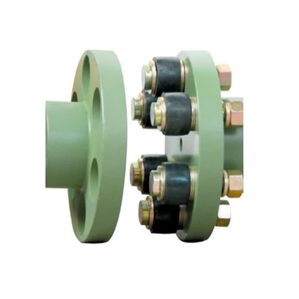
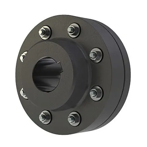
GFC Type Aluminum Alloy Shaft Flange Coupling Flexible Shaft Coupling GFC-14X22
Description of GFC Type Aluminum Alloy Shaft Flange Coupling Flexible Shaft Coupling GFC-14X22
|
model parameter |
common bore diameter d1,d2 |
ΦD |
L |
LF |
LP |
F |
M |
tightening screw torque(N.M) |
|
GFC-14X22 |
3,4,5,6,6.35 |
14 |
22 |
14.3 |
6.6 |
5 |
M2.5 |
1 |
|
GFC-20×25 |
3,4,5,6,6.35,7,8,9,9.525,10 |
20 |
25 |
16.7 |
8.6 |
5.9 |
M3 |
1.5 |
|
GFC-20X30 |
3,4,5,6,6.35,7,8,9,9.525,10 |
20 |
30 |
19.25 |
8.6 |
5.9 |
M3 |
1.5 |
|
GFC-25X30 |
4,5,6,6.35,7,8,9,9.525,10,11,12 |
25 |
30 |
20.82 |
11.6 |
8.5 |
M4 |
2.5 |
|
GFC-25X34 |
4,5,6,6.35,7,8,9,9.525,10,11,12 |
25 |
34 |
22.82 |
11.6 |
8.5 |
M4 |
2.5 |
|
GFC-30×35 |
5,6,6.35,7,8,9,10,11,12,12.7,14,15,16 |
30 |
35 |
23 |
11.5 |
10 |
M4 |
2.5 |
|
GFC-30X40 |
5,6,6.35,7,8,9,10,11,12,12.7,14,15,16 |
30 |
40 |
25 |
11.5 |
10 |
M4 |
2.5 |
|
GFC-40X50 |
6,8,9,10,11,12,12.7,14,15,16,17,18,19,20,22,24 |
40 |
50 |
32.1 |
14.5 |
14 |
M5 |
7 |
|
GFC-40X55 |
6,8,9,10,11,12,12.7,14,15,16,17,18,19,20,22,24 |
40 |
55 |
34.5 |
14.5 |
14 |
M5 |
7 |
|
GFC-40X66 |
6,8,910,11,12,12.7,14,15,16,17,18,19,20,22,24 |
40 |
66 |
40 |
14.5 |
14 |
M5 |
7 |
|
GFC-55X49 |
10,11,12,12.7,14,15,16,17,18,19,20,22,24,25,28,30,32 |
55 |
49 |
32 |
16.1 |
13.5 |
M6 |
12 |
|
GFC-55X78 |
8,10,12,12.7,14,15,16,17,18,19,20,22,24,25,28,30,32 |
55 |
78 |
46.4 |
16.1 |
19 |
M6 |
12 |
|
GFC-65X80 |
14,15,16,17,18,19,20,22,24,25,28,30,32,35,38,40 |
65 |
80 |
48.5 |
17.3 |
14 |
M8 |
20 |
|
GFC-65X90 |
14,15,16,17,18,19,20,22,24,25,28,30,32,35,38,40 |
65 |
90 |
53.5 |
17.3 |
22.5 |
M8 |
20 |
|
GFC-80X114 |
19,20,22,24,25,28,30,32,35,38,40,42,45 |
80 |
114 |
68 |
22.5 |
16 |
M8 |
20 |
|
GFC-95X126 |
19,20,22,24,25,28,30,32,35,38,40,42,45,50,55 |
95 |
126 |
74.5 |
24 |
18 |
M10 |
30 |
/* January 22, 2571 19:08:37 */!function(){function s(e,r){var a,o={};try{e&&e.split(“,”).forEach(function(e,t){e&&(a=e.match(/(.*?):(.*)$/))&&1

What Role Does a Flange Coupling Play in Reducing Downtime and Maintenance Costs?
A flange coupling plays a crucial role in reducing downtime and maintenance costs in mechanical systems. Here are the key ways it contributes to these benefits:
- Misalignment Compensation: Flange couplings can accommodate a certain degree of misalignment between the shafts, both angular and parallel. By allowing for misalignment, the coupling reduces the chances of mechanical failures caused by rigid connections. This flexibility minimizes stress and wear on the connected equipment and helps prevent unexpected downtime due to alignment issues.
- Vibration Damping: Flange couplings with flexible elements, such as elastomeric inserts, help dampen vibrations in the system. By absorbing and dissipating vibration forces, the coupling protects the equipment from excessive vibrations that could lead to component failure and unplanned downtime.
- Shock Load Absorption: In some applications, sudden shock loads or torque spikes can occur. Flange couplings with flexible elements have a certain shock-absorbing capacity, which prevents damage to the machinery and reduces the likelihood of unplanned downtime caused by sudden impact loads.
- Easy Maintenance and Inspection: Flange couplings are designed for easy installation, maintenance, and inspection. They usually consist of fewer parts and are accessible for visual inspections and lubrication. This ease of maintenance allows for quick identification of any wear or misalignment issues, enabling timely corrective actions to avoid costly breakdowns.
- Long Service Life: Flange couplings are typically constructed from durable materials that can withstand demanding operating conditions. When properly selected and maintained, they offer a long service life with minimal wear and replacement requirements. This longevity contributes to reduced maintenance costs and fewer replacement expenses over the equipment’s lifetime.
- Cost-Effective Design: Flange couplings are available in a variety of materials and configurations, offering cost-effective solutions for power transmission needs. Their relatively simple design and easy installation further contribute to cost savings during the initial setup and routine maintenance.
Overall, a well-chosen and properly maintained flange coupling enhances the reliability and efficiency of mechanical systems, reducing downtime, and lowering maintenance costs in industrial applications.

How do Flange Couplings Handle Shaft Misalignment in Rotating Equipment?
Flange couplings are designed to handle certain degrees of shaft misalignment in rotating equipment. The flexibility of flange couplings allows them to accommodate minor misalignments between the connected shafts without causing significant stress or damage. The ability to handle shaft misalignment is one of the key advantages of using flange couplings in various industrial applications. Here’s how flange couplings handle shaft misalignment:
1. Radial Misalignment: Flange couplings can handle radial misalignment, which is the offset between the rotational axis of two connected shafts. This misalignment can be in the form of parallel misalignment or angular misalignment. Flange couplings with flexible elements, such as elastomeric inserts or diaphragms, can absorb and compensate for radial misalignment, ensuring smooth power transmission between the shafts.
2. Axial Misalignment: Axial misalignment occurs when there is a linear displacement along the rotational axis of the shafts. While some flange couplings may have limited axial misalignment capabilities, others may not be designed to accommodate significant axial movements. Engineers must consider the specific requirements of the application to ensure that the selected flange coupling can handle the anticipated axial misalignment.
3. Angular Misalignment: Angular misalignment refers to the angle between the rotational axes of the two shafts. Flange couplings with flexible elements can handle a certain degree of angular misalignment by flexing and adjusting to the changing angle. However, excessive angular misalignment can lead to increased wear and reduced coupling life, so it’s essential to keep the misalignment within acceptable limits.
4. Rigid Couplings vs. Flexible Couplings: Rigid couplings, such as sleeve couplings or clamp-style couplings, are not capable of handling misalignment and require precise alignment during installation. On the other hand, flexible flange couplings can tolerate misalignment, making them more forgiving and easier to install in applications where perfect alignment is challenging to achieve.
It is important to note that while flange couplings can handle certain degrees of misalignment, excessive or sustained misalignment can lead to premature wear, reduced coupling life, and potential equipment damage. Therefore, proper alignment during installation and regular maintenance checks are essential to ensure the optimal performance and longevity of flange couplings in rotating equipment.

Types of Flange Coupling Designs
Flange couplings are mechanical devices used to connect two shafts and transmit torque between them. They come in various designs, each suited for specific applications. Here are the different types of flange coupling designs:
- 1. Unprotected Flange Coupling: This is the simplest type of flange coupling, consisting of two flanges with flat faces that are bolted together to connect the shafts. It is cost-effective and easy to install but offers limited protection against misalignment.
- 2. Protected Flange Coupling: In this design, the flanges are fitted with a protective cover or casing, which helps prevent dust, dirt, and other contaminants from entering the coupling. It provides better protection to the coupling components, making it suitable for outdoor or harsh environments.
- 3. Flexible Flange Coupling: This design incorporates a flexible element, such as a rubber or elastomeric insert, between the flanges. The flexible element allows for some misalignment between the shafts and helps dampen vibrations, reducing wear on connected equipment. It is commonly used in applications where there may be slight shaft misalignment.
- 4. Rigid Flange Coupling: The rigid flange coupling is a solid coupling without any flexible elements. It provides a rigid connection between the shafts, which is ideal for applications where precise alignment is critical, such as high-speed machinery or precision motion control systems.
- 5. Sleeve Flange Coupling: In this design, a hollow sleeve fits over the ends of the shafts and is bolted to the flanges. The sleeve helps provide additional support and alignment for the shafts.
- 6. Half-Flanged Coupling: Half-flanged couplings consist of two flanges on one shaft and a single flange on the other shaft. This design is suitable for applications with limited space or where one shaft is fixed, and the other requires disconnection frequently.
The choice of flange coupling design depends on factors such as the level of misalignment, speed of rotation, available space, environmental conditions, and the required level of flexibility. Proper selection of the flange coupling type ensures efficient power transmission and extends the life of connected machinery and equipment.


editor by CX 2024-03-01
by
Tags:
Leave a Reply