Product Description
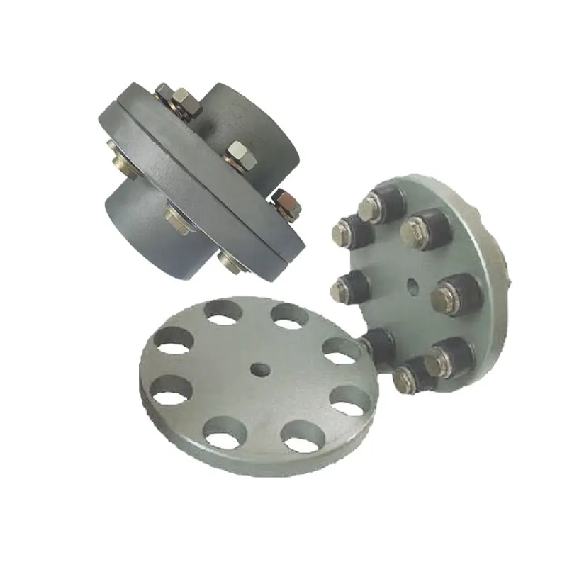
GFC-20×25 Type Aluminum Alloy Shaft Flange Coupling Flexible Shaft Coupling
Description of GFC-20×25 Type Aluminum Alloy Shaft Flange Coupling Flexible Shaft Coupling
| model parameter | common bore diameter d1,d2 | ΦD | L | LF | LP | F | M | tightening screw torque (N.M) |
| GFC-14X22 | 3,4,5,6,6.35 | 14 | 22 | 14.3 | 6.6 | 5.0 | M2.5 | 1.0 |
| GFC-20×25 | 3,4,5,6,6.35,7,8,9,9.525,10 | 20 | 25 | 16.7 | 8.6 | 5.9 | M3 | 1.5 |
| GFC-20X30 | 3,4,5,6,6.35,7,8,9,9.525,10 | 20 | 30 | 19.25 | 8.6 | 5.9 | M3 | 1.5 |
| GFC-25X30 | 4,5,6,6.35,7,8,9,9.525,10,11,12 | 25 | 30 | 20.82 | 11.6 | 8.5 | M4 | 2.5 |
| GFC-25X34 | 4,5,6,6.35,7,8,9,9.525,10,11,12 | 25 | 34 | 22.82 | 11.6 | 8.5 | M4 | 2.5 |
| GFC-30×35 | 5,6,6.35,7,8,9,10,11,12,12.7,14,15,16 | 30 | 35 | 23 | 11.5 | 10 | M4 | 2.5 |
| GFC-30X40 | 5,6,6.35,7,8,9,10,11,12,12.7,14,15,16 | 30 | 40 | 25 | 11.5 | 10 | M4 | 2.5 |
| GFC-40X50 | 6,8,9,10,11,12,12.7,14,15,16,17,18,19,20,22,24 | 40 | 50 | 32.1 | 14.5 | 14 | M5 | 7 |
| GFC-40X55 | 6,8,9,10,11,12,12.7,14,15,16,17,18,19,20,22,24 | 40 | 55 | 34.5 | 14.5 | 14 | M5 | 7 |
| GFC-40X66 | 6,8,910,11,12,12.7,14,15,16,17,18,19,20,22,24 | 40 | 66 | 40 | 14.5 | 14 | M5 | 7 |
| GFC-55X49 | 10,11,12,12.7,14,15,16,17,18,19,20,22,24,25,28,30,32 | 55 | 49 | 32 | 16.1 | 13.5 | M6 | 12 |
| GFC-55X78 | 8,10,12,12.7,14,15,16,17,18,19,20,22,24,25,28,30,32 | 55 | 78 | 46.4 | 16.1 | 19 | M6 | 12 |
| GFC-65X80 | 14,15,16,17,18,19,20,22,24,25,28,30,32,35,38,40 | 65 | 80 | 48.5 | 17.3 | 14 | M8 | 20 |
| GFC-65X90 | 14,15,16,17,18,19,20,22,24,25,28,30,32,35,38,40 | 65 | 90 | 53.5 | 17.3 | 22.5 | M8 | 20 |
| GFC-80X114 | 19,20,22,24,25,28,30,32,35,38,40,42,45 | 80 | 114 | 68 | 22.5 | 16 | M8 | 20 |
| GFC-95X126 | 19,20,22,24,25,28,30,32,35,38,40,42,45,50,55 | 95 | 126 | 74.5 | 24 | 18 | M10 | 30 |
| model parameter | Rated torque (N.M)* |
allowable eccentricity (mm)* |
allowable deflection angle (°)* |
allowable axial deviation (mm)* |
maximum speed rpm |
static torsional stiffness (N.M/rad) |
moment of inertia (Kg.M2) |
Material of shaft sleeve | Material of shrapnel | surface treatment | weight (g) |
| GFC-14X22 | 5.0 | 0.1 | 1 | ±02 | 10000 | 50 | 1.0×10⁻⁶ | High strength aluminum alloy | Polyurethane imported from Germany | Anodizing treatment | 10 |
| GFC-20X25 | 5.0 | 0.1 | 1 | ±02 | 10000 | 50 | 1.0×10⁻⁶ | 15 | |||
| GFC-20X30 | 5.0 | 0.1 | 1 | ^02 | 10000 | 53 | 1.1×10⁻⁶ | 19 | |||
| GFC-25X30 | 10 | 0.1 | 1 | 10000 | 90 | 5.2X10⁻⁶ | 33 | ||||
| GFC-25X34 | 10 | 0.1 | 1 | £)2 | 10000 | 90 | 5.2×10⁻⁶ | 42 | |||
| GFC-30X35 | 12.5 | 0.1 | 1 | ±02 | 10000 | 123 | 6.2×10⁻⁶ | 50 | |||
| GFC-30×40 | 12.5 | 0.1 | 1 | 102 | 10000 | 123 | 6.2×10⁻⁶ | 60 | |||
| GFC-40X50 | 17 | 0.1 | 1 | 8000 | 1100 | 3.8×10⁻⁵ | 115 | ||||
| GFC-40X55 | 17 | 0.1 | 1 | ±02 | 8000 | 1100 | 3.8×10⁻⁵ | 127 | |||
| GFC-40X66 | 17 | 0.1 | 1 | 7000 | 1140 | 3.9×10⁻⁵ | 154 | ||||
| GFC-55X49 | 45 | 0.1 | 1 | ±02 | 6500 | 2350 | 1.6×10⁻³ | 241 | |||
| GFC-55X78 | 45 | 0.1 | 1 | 102 | 6000 | 2500 | 1.6×10⁻³ | 341 | |||
| GFC-65X80 | 108 | 0.1 | 1 | ±02 | 5500 | 4500 | 3.8×10⁻³ | 433 | |||
| GFC-65X90 | 108 | 0.1 | 1 | ±02 | 5500 | 4800 | 3.8×10⁻³ | 583 | |||
| GFC-80X114 | 145 | 0.1 | 1 | £)2 | 4500 | 5000 | 1.8×10⁻³ | 1650 | |||
| GFC-95X126 | 250 | 0.1 | 1 | ±02 | 4000 | 5000 | 2.0×10⁻³ | 1000 |
/* January 22, 2571 19:08:37 */!function(){function s(e,r){var a,o={};try{e&&e.split(“,”).forEach(function(e,t){e&&(a=e.match(/(.*?):(.*)$/))&&1

Differences Between Rigid and Flexible Flange Coupling Designs
Flange couplings are essential components used in various mechanical systems to connect shafts and transmit power between them. Two common types of flange coupling designs are rigid flange couplings and flexible flange couplings. These designs differ in their construction and performance characteristics:
Rigid Flange Couplings:
Rigid flange couplings are designed to provide a solid and inflexible connection between two shafts. They are suitable for applications where shaft alignment is precise, and no misalignment is expected during operation. The key features of rigid flange couplings include:
- Stiff Construction: Rigid flange couplings are made from robust materials such as steel or aluminum. Their stiffness ensures that there is little to no flexibility, maintaining a solid connection between the shafts.
- No Misalignment Compensation: Rigid flange couplings do not accommodate any misalignment between the shafts. Therefore, proper alignment is crucial during installation to prevent undue stress on the shafts and connected equipment.
- High Torque Transmission: Due to their rigid design, rigid flange couplings offer high torque transmission capabilities, making them suitable for heavy-duty applications with precise alignment requirements.
Flexible Flange Couplings:
Flexible flange couplings, as the name suggests, offer some degree of flexibility and misalignment compensation between the connected shafts. They are used in applications where shaft misalignment, caused by factors like vibration, temperature changes, or minor installation errors, is likely to occur. The key features of flexible flange couplings include:
- Misalignment Compensation: Flexible flange couplings can tolerate angular, parallel, and axial misalignment to some extent. This helps to reduce stress on the connected equipment and enhances the overall performance and lifespan of the system.
- Vibration Dampening: The flexibility of these couplings allows them to dampen vibrations and shocks, making them suitable for systems where vibrations are a concern.
- Reduced Stress on Bearings: Flexible flange couplings can help reduce the stress on bearings and other connected components by absorbing misalignment forces.
When choosing between rigid and flexible flange couplings, it is essential to consider the specific requirements of the application. Rigid flange couplings are best suited for applications with precise alignment, while flexible flange couplings are ideal for systems where some degree of misalignment is expected. The selection process should also take into account factors such as torque capacity, shaft sizes, operating conditions, and maintenance requirements.
In conclusion, the choice between rigid and flexible flange coupling designs depends on the application’s alignment needs and the desired level of misalignment compensation and vibration dampening.
Maintenance-Free Flange Couplings
Flange couplings can be designed to be maintenance-free, meaning they require minimal or no regular maintenance throughout their operational life. The key features and options that contribute to maintenance-free flange couplings include:
- Sealed and Lubricated: Some flange couplings are sealed and pre-lubricated with high-performance grease during the manufacturing process. This ensures that the coupling remains properly lubricated over an extended period, eliminating the need for routine lubrication.
- Self-Lubricating Materials: Certain flange couplings are constructed from self-lubricating materials, such as polymers or composites, that provide a low-friction interface between the mating surfaces. This reduces wear and eliminates the need for additional lubrication.
- Maintenance-Free Bearings: Flange couplings with integrated maintenance-free bearings further enhance the overall maintenance-free operation. These bearings are designed to withstand the required loads and provide long-lasting performance without the need for regular lubrication.
- Corrosion-Resistant Materials: Flange couplings made from corrosion-resistant materials, such as stainless steel or coated alloys, can resist environmental factors that might lead to corrosion and premature wear, resulting in extended maintenance intervals.
- Robust Design: A well-engineered flange coupling with a robust design can withstand harsh conditions, shock loads, and other stresses, reducing the likelihood of component failure and the need for maintenance.
It is essential to select a flange coupling that is specifically labeled as “maintenance-free” or “self-lubricating” by the manufacturer to ensure that it meets your maintenance objectives. However, it’s important to note that even maintenance-free flange couplings may still require periodic inspection to check for wear, alignment issues, or other potential problems.
Can Flange Couplings Handle Misalignment Between Shafts?
Flange couplings are designed to handle a limited amount of misalignment between shafts. However, their ability to accommodate misalignment is more limited compared to flexible couplings.
The misalignment that flange couplings can tolerate is typically in the form of angular misalignment and axial misalignment. Angular misalignment occurs when the axes of the two shafts are not perfectly aligned, causing the flanges to be at an angle to each other. Axial misalignment, on the other hand, refers to the displacement of one shaft along its axis with respect to the other shaft.
It is essential to note that excessive misalignment can lead to increased stress on the coupling and connected equipment. Flange couplings may not be suitable for applications with significant misalignment requirements.
For applications that involve substantial misalignment or require flexibility to accommodate misalignment, flexible couplings are more appropriate. Flexible couplings, such as elastomeric or jaw couplings, can handle both angular and axial misalignment more effectively than rigid flange couplings.
In summary, while flange couplings can handle some degree of misalignment, their primary strength lies in their ability to transmit high torques and withstand heavy loads in more rigidly aligned shaft arrangements. When dealing with misalignment-sensitive systems, it is best to consider flexible coupling options to ensure optimal performance and prevent premature wear on the equipment.


editor by CX 2024-03-04
by
Tags:
Leave a Reply