Product Description
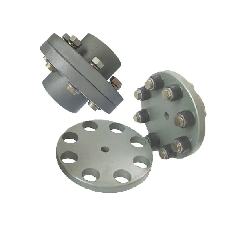
LMD Single Flange Type Plum Elastic Coupling(GB/T 5272-2002)
♦Description
Plum elastic coupling has the characteristics of vibration reduction, buffering, small radial size, no lubrication, and easy maintenance. Suitable for starting frequency, positive and negative rotation, medium and low speed, medium and small power transmission.Not suitable for heavy loads and frequent replacement of elastic elements.
The structure of plum elastic coupling is simple. But when the elastic element is replaced, the half coupling shall be moved axially.LMS type easily replaces the elastic element without having to move the half coupling.
♦Basic Parameter and Main Dimension
| Type | Norminal torque(Tn/N·m) | Speed(Np) | Shaft hole diameter (d1,d2,dz) |
Length of the shaft hole | LO | D | D1 | Type of elastic parts | Mass | Rotary inertia | ||||||||||||||
| The hardness of elastic parts | LM | LMD, LMS | Y type | J1,Z type | L (recommend) |
LM | LMD | LMS | LMD, LMS | LM | LMD | LMS | LM | LMD | LMS | |||||||||
| a/HA | b/HD | L | ||||||||||||||||||||||
| 80+5 | 60+5 | r·min-1 | Mm | kg | kg·m2 | |||||||||||||||||||
| LM1 LMD1 LMS1 |
25 | 45 | 15300 | 8500 | 12,14 | 32 | 27 | 35 | 86 | 92 | 98 | 50 | 90 | MT1-a -b | 0.66 | 1.21 | 1.33 | 0.0002 | 0.0008 | 0.0013 | ||||
| 16,18,19 | 42 | 30 | ||||||||||||||||||||||
| 20,22,24 | 52 | 38 | ||||||||||||||||||||||
| 25 | 62 | 44 | ||||||||||||||||||||||
| LM2 LMD2 LMS2 |
50 | 100 | 1200 | 7600 | 16,18,19 | 42 | 30 | 38 | 95 | 101.5 | 108 | 60 | 100 | MT2-a -b | 0.93 | 1.65 | 1.74 | 0.0004 | 0.0014 | 0.0571 | ||||
| 20,22,24 | 52 | 38 | ||||||||||||||||||||||
| 25,28 | 62 | 44 | ||||||||||||||||||||||
| 30 | 82 | 60 | ||||||||||||||||||||||
| LM3 LMD3 LMS3 |
100 | 200 | 10900 |
6900 | 20,22,24 | 52 | 38 | 40 | 103 | 110 | 117 | 70 | 110 | MT3-a -b | 1.41 | 2.36 | 2.33 | 0.0009 | 0.0571 | 0.0034 | ||||
| 25,28 | 62 | 44 | ||||||||||||||||||||||
| 30,32 | 82 | 60 | ||||||||||||||||||||||
| LM4 LMD4 LMS4 |
140 | 280 | 9000 |
6200 | 22,24 | 52 | 38 | 45 | 114 | 122 | 130 | 85 | 125 | MT4-a -b | 2.18 | 3.56 | 3.38 | 0.002 | 0.005 | 0.0064 | ||||
| 25,28 | 62 | 44 | ||||||||||||||||||||||
| 30,32,35,38 | 82 | 60 | ||||||||||||||||||||||
| 40 | 112 | 84 | ||||||||||||||||||||||
| LM5 LMD5 LMS5 |
350 | 400 | 7300 |
5000 | 25,28 | 62 | 44 | 50 | 127 | 138.5 | 150 | 105 | 150 | MT5-a -b | 3.60 | 6.36 | 6.07 | 0.005 | 0.0135 | 0.0175 | ||||
| 30,32,35,38 | 82 | 60 | ||||||||||||||||||||||
| 40,42,45 | 112 | 84 | ||||||||||||||||||||||
| LM6 LMD6 LMS6 |
400 | 710 | 6100 |
4100 | 30,32,35,38 | 82 | 60 | 55 | 143 | 155 | 167 | 185 | 185 | MT6-a -b | 6.07 | 10.77 | 10.47 | 0.0114 | 0.0329 | 0.0444 | ||||
| 40,42,45,48 | 112 | 84 | ||||||||||||||||||||||
| LM7 LMD7 LMS7 |
630 | 1120 | 5300 | 3700 | 35*,38* | 82 | 60 | 60 | 159 | 172 | 185 | 205 | 205 | MT7-a -b | 9.09 | 15.30 | 14.22 | 0.5712 | 0.0581 | 0.571 | ||||
| 40*,42*,45,48,50,55 | 112 | 84 | ||||||||||||||||||||||
| LM8 LMD8 LMS8 |
1120 | 2240 | 4500 | 3100 | 45*,48*,50,55,56 | 112 | 84 | 70 | 181 | 195 | 209 | 170 | 240 | MT8-a -b | 13.56 | 22.72 | 21.16 | 0. 0571 | 0.1175 | 0.1493 | ||||
| 60,63,65 | 142 | 107 | ||||||||||||||||||||||
| LM9 LMD9 LMS9 |
1800 | 3550 | 3800 | 2800 | 50*,55*,56* | 112 | 84 | 80 | 208 | 224 | 240 | 200 | 270 | MT9-a -b | 21.40 | 34.44 | 30.70 | 0.1041 | 0.2333 | 0.2767 | ||||
| 60,63,65,70,71,75 | 142 | 107 | ||||||||||||||||||||||
| 80 | 172 | 132 | ||||||||||||||||||||||
| LM10 LMD10 LMS10 |
2800 | 5600 | 3300 | 2500 | 60*,63*,65*,70,71,75 | 142 | 107 | 90 | 230 | 248 | 268 | 230 | 305 | MT10-a -b | 32.03 | 51.36 | 44.55 | 0.2105 | 0.4594 | 0.5262 | ||||
| 80,85,90,95 | 172 | 132 | ||||||||||||||||||||||
| 100 | 212 | 167 | ||||||||||||||||||||||
| LM11 LMD11 LMS11 |
4500 | 9000 | 2900 | 2200 | 71*,71*,75* | 142 | 107 | 100 | 260 | 284 | 308 | 260 | 350 | MT11-a -b | 49.52 | 81.30 | 70.72 | 0.4338 | 0.9777 | 1.1362 | ||||
| 80*,85*,90,95 | 172 | 132 | ||||||||||||||||||||||
| 100,110,120 | 212 | 167 | ||||||||||||||||||||||
| LM12 LMD12 LMS12 |
6300 | 12500 | 2500 | 1900 | 80*,85*,90*95 | 172 | 132 | 115 | 297 | 321 | 345 | 300 | 400 | MT12-a -b | 73.45 | 115.53 | 99.54 | 0.8205 | 1.751 | 1.9998 | ||||
| 100,110,120,125 | 212 | 167 | ||||||||||||||||||||||
| 130,140,150 | 252 | 202 | ||||||||||||||||||||||
| LM13 LMD13 LMS13 |
11200 | 2000 | 2100 | 1600 | 90*,95* | 172 | 132 | 125 | 323 | 348 | 373 | 360 | 460 | MT13-a -b | 103.86 | 161.79 | 137.53 | 1.6718 | 3.667 | 3.6719 | ||||
| 100*,110*,120*,125* | 212 | 167 | ||||||||||||||||||||||
| 130,140,150 | 252 | 202 | ||||||||||||||||||||||
| LM14 LMD14 LMS14 |
12500 | 25000 | 1900 | 1500 | 100*,110*,120*,125* | 212 | 167 | 135 | 333 | 358 | 383 | 400 | 500 | MT14-a -b | 127.59 | 196.32 | 165.25 | 2.499 | 4.8669 | 5.1581 | ||||
| 130*,140*,150 | 252 | 202 | ||||||||||||||||||||||
| 160 | 302 | 242 | ||||||||||||||||||||||
NOTE:
1. Mass and rotary inertia are the approximation calculated according to the recommended minimum axial hole.
2. Diameter of shaft hole with * can be used for Z – type shaft hole.
3. a.b is the code for 2 different materials and the hardness of elastic parts.
♦Other Products List
| Transmission Machinery Parts Name |
Model |
| Universal Coupling | WS,WSD,WSP |
| Cardan Shaft | SWC,SWP,SWZ |
| Tooth Coupling | CL,CLZ,GCLD,GIICL, GICL,NGCL,GGCL,GCLK |
| Disc Coupling | JMI,JMIJ,JMII,JMIIJ |
| High Flexible Coupling | LM |
| Chain Coupling | GL |
| Jaw Coupling | LT |
| Grid Coupling | JS |
Company Profile
♦Our Company
HangZhou CHINAMFG Machinery Manufacturing Co., Ltd. is a high-tech enterprise specializing in the design and manufacture of various types of coupling. There are 86 employees in our company, including 2 senior engineers and no fewer than 20 mechanical design and manufacture, heat treatment, welding, and other professionals.
Advanced and reasonable process, complete detection means. Our company actively introduces foreign advanced technology and equipment, on the basis of the condition, we make full use of the advantage and do more research and innovation. Strict to high quality and operate strictly in accordance with the ISO9000 quality certification system standard mode.
Our company supplies different kinds of products. High quality and reasonable price. We stick to the principle of “quality first, service first, continuous improvement and innovation to meet the customers” for the management and “zero defect, zero complaints” as the quality objective.
♦Our Services
1. Design Services
Our design team has experience in Cardan shafts relating to product design and development. If you have any needs for your new product or wish to make further improvements, we are here to offer our support.
2. Product Services
Raw materials → Cutting → Forging →Rough machining →Shot blasting →Heat treatment →Testing →Fashioning →Cleaning→ Assembly→ Packing→ Shipping
3. Samples Procedure
We could develop the sample according to your requirement and amend the sample constantly to meet your need.
4. Research & Development
We usually research the new needs of the market and develop the new model when there is new cars in the market.
5. Quality Control
Every step should be a special test by Professional Staff according to the standard of ISO9001 and TS16949.
♦FAQ
Q 1: Are you a trading company or a manufacturer?
A: We are a professional manufacturer specializing in manufacturing various series of couplings.
Q 2: Can you do OEM?
Yes, we can. We can do OEM & ODM for all the customers with customized artworks in PDF or AI format.
Q 3: How long is your delivery time?
Generally, it is 20-30 days if the goods are not in stock. It is according to quantity.
Q 4: Do you provide samples? Is it free or extra?
Yes, we could offer the sample but not for free. Actually, we have a very good price principle, when you make the bulk order the cost of the sample will be deducted.
Q 5: How long is your warranty?
A: Our Warranty is 12 months under normal circumstances.
Q 6: What is the MOQ?
A: Usually our MOQ is 1 pcs.
Q 7: Do you have inspection procedures for coupling?
A: 100% self-inspection before packing.
Q 8: Can I have a visit to your factory before the order?
A: Sure, welcome to visit our factory.
Q 9: What’s your payment?
A: T/T.
♦Contact Us
Web: huadingcoupling
Add: No.11 HangZhou Road,Chengnan park,HangZhou City,ZheJiang Province,China
/* January 22, 2571 19:08:37 */!function(){function s(e,r){var a,o={};try{e&&e.split(“,”).forEach(function(e,t){e&&(a=e.match(/(.*?):(.*)$/))&&1

Differences Between Rigid and Flexible Flange Coupling Designs
Flange couplings are essential components used in various mechanical systems to connect shafts and transmit power between them. Two common types of flange coupling designs are rigid flange couplings and flexible flange couplings. These designs differ in their construction and performance characteristics:
Rigid Flange Couplings:
Rigid flange couplings are designed to provide a solid and inflexible connection between two shafts. They are suitable for applications where shaft alignment is precise, and no misalignment is expected during operation. The key features of rigid flange couplings include:
- Stiff Construction: Rigid flange couplings are made from robust materials such as steel or aluminum. Their stiffness ensures that there is little to no flexibility, maintaining a solid connection between the shafts.
- No Misalignment Compensation: Rigid flange couplings do not accommodate any misalignment between the shafts. Therefore, proper alignment is crucial during installation to prevent undue stress on the shafts and connected equipment.
- High Torque Transmission: Due to their rigid design, rigid flange couplings offer high torque transmission capabilities, making them suitable for heavy-duty applications with precise alignment requirements.
Flexible Flange Couplings:
Flexible flange couplings, as the name suggests, offer some degree of flexibility and misalignment compensation between the connected shafts. They are used in applications where shaft misalignment, caused by factors like vibration, temperature changes, or minor installation errors, is likely to occur. The key features of flexible flange couplings include:
- Misalignment Compensation: Flexible flange couplings can tolerate angular, parallel, and axial misalignment to some extent. This helps to reduce stress on the connected equipment and enhances the overall performance and lifespan of the system.
- Vibration Dampening: The flexibility of these couplings allows them to dampen vibrations and shocks, making them suitable for systems where vibrations are a concern.
- Reduced Stress on Bearings: Flexible flange couplings can help reduce the stress on bearings and other connected components by absorbing misalignment forces.
When choosing between rigid and flexible flange couplings, it is essential to consider the specific requirements of the application. Rigid flange couplings are best suited for applications with precise alignment, while flexible flange couplings are ideal for systems where some degree of misalignment is expected. The selection process should also take into account factors such as torque capacity, shaft sizes, operating conditions, and maintenance requirements.
In conclusion, the choice between rigid and flexible flange coupling designs depends on the application’s alignment needs and the desired level of misalignment compensation and vibration dampening.
Maintenance-Free Flange Couplings
Flange couplings can be designed to be maintenance-free, meaning they require minimal or no regular maintenance throughout their operational life. The key features and options that contribute to maintenance-free flange couplings include:
- Sealed and Lubricated: Some flange couplings are sealed and pre-lubricated with high-performance grease during the manufacturing process. This ensures that the coupling remains properly lubricated over an extended period, eliminating the need for routine lubrication.
- Self-Lubricating Materials: Certain flange couplings are constructed from self-lubricating materials, such as polymers or composites, that provide a low-friction interface between the mating surfaces. This reduces wear and eliminates the need for additional lubrication.
- Maintenance-Free Bearings: Flange couplings with integrated maintenance-free bearings further enhance the overall maintenance-free operation. These bearings are designed to withstand the required loads and provide long-lasting performance without the need for regular lubrication.
- Corrosion-Resistant Materials: Flange couplings made from corrosion-resistant materials, such as stainless steel or coated alloys, can resist environmental factors that might lead to corrosion and premature wear, resulting in extended maintenance intervals.
- Robust Design: A well-engineered flange coupling with a robust design can withstand harsh conditions, shock loads, and other stresses, reducing the likelihood of component failure and the need for maintenance.
It is essential to select a flange coupling that is specifically labeled as “maintenance-free” or “self-lubricating” by the manufacturer to ensure that it meets your maintenance objectives. However, it’s important to note that even maintenance-free flange couplings may still require periodic inspection to check for wear, alignment issues, or other potential problems.

Selecting the Appropriate Flange Coupling for a Specific Application
Choosing the right flange coupling for a particular application involves considering several key factors to ensure optimal performance and reliability. Here’s a step-by-step guide to the selection process:
- 1. Identify Application Requirements: Understand the specific requirements of the application, including torque, speed, and operating conditions. Determine if the coupling will be exposed to harsh environments, extreme temperatures, or corrosive substances.
- 2. Calculate Torque and Power: Calculate the torque and power requirements for the shaft connection. This involves evaluating the motor or engine’s output torque and ensuring the selected coupling can handle the transmitted power.
- 3. Consider Misalignment: Assess the level of misalignment that may occur between the shafts during operation. For applications with significant misalignment, consider using flexible flange couplings that can accommodate angular, parallel, and axial misalignment.
- 4. Evaluate Speed and RPM: Determine the rotational speed (RPM) at which the coupling will operate. High-speed applications may require a balanced or precision-designed flange coupling to minimize vibrations and prevent damage to connected equipment.
- 5. Check Space Constraints: Consider the available space for installing the coupling. Some flange coupling designs may require more space than others, so ensure that the selected coupling fits within the available area.
- 6. Review Environmental Conditions: Evaluate the environmental conditions in which the coupling will operate. If the application involves exposure to dust, dirt, or moisture, consider using a protected or sealed flange coupling to prevent contamination.
- 7. Determine Flexibility: Decide on the level of flexibility required. Flexible flange couplings are suitable for applications where there may be shaft misalignment or torsional vibration. Rigid flange couplings, on the other hand, are ideal for precision applications with minimal misalignment.
- 8. Check Material Compatibility: Ensure that the material of the flange coupling is compatible with the shafts and the operating environment. Consider factors such as corrosion resistance, temperature tolerance, and mechanical properties.
- 9. Seek Expert Advice: When in doubt, consult with coupling manufacturers or engineering experts to help you select the most suitable flange coupling for your specific application.
By carefully considering these factors, you can select the appropriate flange coupling that meets the performance and operational requirements of your application, leading to a reliable and efficient shaft connection.


editor by CX 2024-04-02
by
Tags:
Leave a Reply