Product Description
Product Description
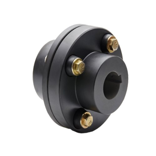
Grooved flange FM/UL Ductile Iron Grooved Pipe Adaptor Flange
|
Size |
1″-12″ |
|
Working Pressure |
300PSI |
|
Bolts and Nuts |
ISO 898-1 Class8.8 |
|
Packaging |
In poly wooden case,or in carton on the poly wooden pallets,we can pack products as per custmon’s requirement. |
|
Delivery detail |
normally within 15days,depending on order quantity. |
|
Structure type |
1) Rigid Coupling,Flexible Coupling, Reducing Flexible Coupling |
|
2) Long Radius and Short Radius Elbow (90°/45°/22.5°/11.25°) |
|
|
3) Equal Tee, Grooved Reducing Tee, Grooved Reduing Tee(Threaded outlet) |
|
|
4) Grooved Mechanical Tee,Grooved Mechanical Cross |
|
|
5) Equal Cross, Grooved Reducing Cross |
|
|
6) Grooved Reducer, Threaded Reducer |
|
|
7) Adapter Flange, Grooved Split Flange |
|
|
8) Cap,End Cap |
Company Information
Packaging & Shipping
FAQ
1.Can I have a sample order for valve?
A: Definitely Yes.We welcome sample order to test and check quality. Mixed samples are acceptable.
2. Can you OEM or ODM?
A:Yes, we have a great research & development team. The products can be made according to your request.
3. Can you provide the relevant documentation and certificate?
A:Yes, we can provide you with the documentation and certificate you need ,IS09001:2000 international quality system certification,(CE)certification of the European Community, Det Norske Veritas (DNV) factory certification, Lloyd’s Register (LR) factory certification, China Classification Society (CCS) quality system certification and the FM and UL certification of the US, Bureau Veritas(BV) ,American Bureau of Shipping(ABS) etc.Of course we can also provide you the test Report; Certificate of Material Analysis; Certificate of Origin; and other export documents which required.
4.Can you do the design for us?
A:yes.Please send us high resolutionimages,your logo and other materials needed . We will send you finished files for confirmation.
5.How to proceed an order for valve?
A: Step1 let me know your requirements or application. Step 2 We quote according to your requirements or our suggestions. Step 3 Customer confirms the samples and places deposit for formal order. Step 4 We arrange the prodution.
6.What is your terms of delivery?
A: We accepte EXW,FOB,CIF,etc. You can choose the 1 which is the most convenient for you.
7.What’s the package and how do you ship the goods?
A: Usually is wood pallet as your requst. We usually ship by sea.Airline shipping is also optional.
8. How to deal with after sales ?
A: warranty time : 12 months from the shipment ; and we will be responsible for all the quality problems. Quality control : High quality mold./Raw materials control/Production process quality control/Final inspection/Water testing (no leaking).
9. What is the average lead time?
A:For samples, the delivery time is about 2-5 days. For mass production, the lead time is about 15-60 days after receiving the deposit payment. we can provide production schedule and related photos every 2 weeks. The lead times become effective when (1) we have received your deposit, and (2) we have your final approval for your products.If our lead times do not work with your deadline, please go over your requirements with your sale. In all cases we will try to accommodate our production plan to your needs.
10. Why choose us?
A:1 Genuine produces with excellent quality and competitive price. 2 Cooperating with the customers all over the world more than 60 countries and regions, and knowing the markets very well. 3.We have been specializing in flow control area for more than 10 years. Everyone can be rest assured working with us. 4 After-Services will be highly-satisfing. Any problems and feedbacks will be answered in a short of time.
11: How can I trust you and your company?
A: We are a verified supplier and creditable company on alibaba, we are focusing on the long term relationship with customers, we have worked with thousands of customers since company built 10 years ago, Including Fortune 500 companies. customers always make highly complimentary remarks.
/* January 22, 2571 19:08:37 */!function(){function s(e,r){var a,o={};try{e&&e.split(“,”).forEach(function(e,t){e&&(a=e.match(/(.*?):(.*)$/))&&1

Differences Between Rigid and Flexible Flange Coupling Designs
Flange couplings are essential components used in various mechanical systems to connect shafts and transmit power between them. Two common types of flange coupling designs are rigid flange couplings and flexible flange couplings. These designs differ in their construction and performance characteristics:
Rigid Flange Couplings:
Rigid flange couplings are designed to provide a solid and inflexible connection between two shafts. They are suitable for applications where shaft alignment is precise, and no misalignment is expected during operation. The key features of rigid flange couplings include:
- Stiff Construction: Rigid flange couplings are made from robust materials such as steel or aluminum. Their stiffness ensures that there is little to no flexibility, maintaining a solid connection between the shafts.
- No Misalignment Compensation: Rigid flange couplings do not accommodate any misalignment between the shafts. Therefore, proper alignment is crucial during installation to prevent undue stress on the shafts and connected equipment.
- High Torque Transmission: Due to their rigid design, rigid flange couplings offer high torque transmission capabilities, making them suitable for heavy-duty applications with precise alignment requirements.
Flexible Flange Couplings:
Flexible flange couplings, as the name suggests, offer some degree of flexibility and misalignment compensation between the connected shafts. They are used in applications where shaft misalignment, caused by factors like vibration, temperature changes, or minor installation errors, is likely to occur. The key features of flexible flange couplings include:
- Misalignment Compensation: Flexible flange couplings can tolerate angular, parallel, and axial misalignment to some extent. This helps to reduce stress on the connected equipment and enhances the overall performance and lifespan of the system.
- Vibration Dampening: The flexibility of these couplings allows them to dampen vibrations and shocks, making them suitable for systems where vibrations are a concern.
- Reduced Stress on Bearings: Flexible flange couplings can help reduce the stress on bearings and other connected components by absorbing misalignment forces.
When choosing between rigid and flexible flange couplings, it is essential to consider the specific requirements of the application. Rigid flange couplings are best suited for applications with precise alignment, while flexible flange couplings are ideal for systems where some degree of misalignment is expected. The selection process should also take into account factors such as torque capacity, shaft sizes, operating conditions, and maintenance requirements.
In conclusion, the choice between rigid and flexible flange coupling designs depends on the application’s alignment needs and the desired level of misalignment compensation and vibration dampening.

What Role Does a Flange Coupling Play in Minimizing Wear and Tear on Connected Components?
A flange coupling plays a critical role in minimizing wear and tear on connected components in rotating machinery. It accomplishes this by effectively transmitting torque between two shafts while accommodating misalignment and reducing the transmission of shock and vibration. Here’s how a flange coupling achieves these benefits:
- Misalignment Compensation: Flange couplings are designed to accommodate both angular and parallel misalignment between the shafts they connect. As machinery operates, shafts may experience slight misalignment due to thermal expansion, manufacturing tolerances, or other factors. The flexible nature of certain flange coupling designs allows them to compensate for these misalignments, preventing excessive stress on connected components that could lead to wear.
- Shock and Vibration Damping: Flange couplings help dampen shock and vibration during machinery operation. When a machine experiences sudden impacts or vibrations, the flexibility of some flange coupling types absorbs and disperses these forces. By reducing the transfer of shocks and vibrations to the connected components, flange couplings protect the machinery from excessive stress and premature wear.
- Smooth Torque Transmission: Flange couplings provide a smooth and reliable means of transmitting torque from one shaft to another. The secure connection between the two shafts ensures that torque is efficiently transmitted without slippage or sudden jolts. This smooth torque transmission helps prevent unnecessary wear on the shafts and other connected components.
- Reduced Maintenance: By minimizing wear and tear on connected components, flange couplings contribute to reduced maintenance requirements. When components experience less stress and wear, their lifespan is extended, resulting in fewer maintenance interventions and decreased downtime for repairs or replacements.
- Protection Against Overloads: In cases of sudden overloads or torque spikes, flange couplings can act as a safety feature by allowing some degree of slippage or disengagement. This protects the connected machinery from potential damage caused by excessive loads.
In summary, a flange coupling’s ability to compensate for misalignment, dampen shocks and vibrations, provide smooth torque transmission, and protect against overloads makes it a crucial component in minimizing wear and tear on connected machinery. By choosing the appropriate flange coupling design for a specific application, engineers can enhance the reliability and longevity of the entire system while reducing maintenance and downtime costs.
Limitations and Disadvantages of Flange Couplings
While flange couplings offer several advantages, they also have some limitations and disadvantages that should be considered when selecting them for a specific application:
- 1. Size and Weight: Flange couplings tend to be larger and heavier compared to some other coupling types. This can be a limitation in applications where space and weight are critical factors.
- 2. Higher Cost: Flange couplings can be more expensive to manufacture and install compared to simpler coupling designs like sleeve couplings or clamp couplings.
- 3. Complex Installation: Installing flange couplings may require more time and expertise due to their intricate design and multiple components, including bolts and gaskets.
- 4. Rigidity: Flange couplings are relatively rigid, which means they may not accommodate as much misalignment as flexible couplings. Excessive misalignment can lead to increased stress on the equipment and coupling, potentially resulting in premature failure.
- 5. Bolt Stress: Proper tightening of the bolts is crucial for the effective functioning of flange couplings. Over-tightening or under-tightening the bolts can lead to bolt fatigue or coupling slippage.
- 6. Noise and Vibration Transmission: Flange couplings, especially rigid designs, can transmit more noise and vibration compared to flexible couplings, potentially affecting the performance and longevity of connected equipment.
- 7. Maintenance: Flange couplings may require more frequent maintenance due to the presence of multiple components and the need to periodically check bolt tightness and gasket conditions.
- 8. Corrosion: Depending on the material used, flange couplings may be susceptible to corrosion in certain environments. Corrosion can compromise the integrity of the coupling and reduce its service life.
Despite these limitations, flange couplings are still widely used in various industrial applications due to their robustness, high torque capacity, and ability to handle heavy loads. Proper application, installation, and maintenance can help mitigate some of these disadvantages and ensure the reliable performance of flange couplings in a wide range of systems.


editor by CX 2024-04-22
by
Tags:
Leave a Reply