Product Description
Key attributes of Customized CNC Machining High Precise transmission Steel Large Spline Gear Shaft
Industry-specific attributes of Customized CNC Machining High Precise transmission Steel Large Spline Gear Shaft
| CNC Machining or Not | Cnc Machining |
| Material Capabilities | Aluminum, Brass, Bronze, Copper, Hardened Metals, Precious Metals, Stainless steel, Steel Alloys |
Other attributes of Customized CNC Machining High Precise transmission Steel Large Spline Gear Shaft
| Place of Origin | ZheJiang , China |
| Type | Broaching, DRILLING, Etching / Chemical Machining, Laser Machining, Milling, Other Machining Services, Turning, Wire EDM |
| Model Number | OEM |
| Brand Name | OEM |
| Material | Metal |
| Process | Cnc Machining+deburrs |
| Surface treatment | Customer’s Request |
| Equipment | CNC Machining Centres / Core moving machine / precision lathe / Automatic loading and unloading equipment |
| Processing Type | Milling / Turning / Stamping |
| OEM/ODM | OEM & ODM CNC Milling Turning Machining Service |
| Drawing Format | 2D/(PDF/CAD)3D(IGES/STEP) |
| Our Service | OEM ODM Customers’drawing |
| Materials Avaliable | Stainless Steel / Aluminum / Metals / Copper / Plastic |
Best Seller of 304 Stainless Steel Polishing Finishing CNC Machining Bracket for Laser Cutting
About YiSheng
| Business Type | Factory / Manufacturer |
| Service | CNC Machining |
| Turning and Milling | |
| CNC Turning | |
| OEM Parts | |
| Material | 1). Aluminum: AL 6061-T6, 6063, 7075-T etc |
| 2). Stainless steel: 303,304,316L, 17-4(SUS630) etc | |
| 3). Steel: 4140, Q235, Q345B,20#,45# etc. | |
| 4). Titanium: TA1,TA2/GR2, TA4/GR5, TC4, TC18 etc | |
| 5). Brass: C36000 (HPb62), C37700 (HPb59), C26800 (H68), C22000(H90) etc | |
| 6). Copper, bronze, Magnesium alloy, Delrin, POM,Acrylic, PC, etc. | |
| Finish | Sandblasting, Anodize color, Blackenning, Zinc/Nickl Plating, Polish, |
| Power coating, Passivation PVD, Titanium Plating, Electrogalvanizing, | |
| electroplating chromium, electrophoresis, QPQ(Quench-Polish-Quench), | |
| Electro Polishing,Chrome Plating, Knurl, Laser etch Logo, etc. | |
| Main Equipment | CNC Machining center, CNC Lathe, precision lathe |
| Automatic loading and unloading equipment | |
| Core moving machine | |
| Drawing format | STEP,STP,GIS,CAD,PDF,DWG,DXF etc or samples. |
| Tolerance | +/-0.001mm ~ +/-0.05mm |
| Surface roughness | Ra 0.1~3.2 |
| Test Equipment | Complete test lab with Projector, High-low temperature test chamber, Tensile tester Gauge, Salt fog test |
| Inspection | Complete inspection lab with Micrometer, Optical Comparator, Caliper Vernier,CMM |
| Depth Caliper Vernier, Universal Protractor, Clock Gauge | |
| Capacity | CNC turning work range: φ0.5mm-φ150mm*300mm |
| CNC center work range: 510mm*850mm*500mm | |
| Core moving machine work range: φ32mm*85mm | |
| Gerenal Tolerance: (+/-mm) |
CNC Machining: 0.005 |
| Core moving: 0.005 | |
| Turning: 0.005 | |
| Grinding(Flatness/in2): 0.003 | |
| ID/OD Grinding: 0.002 | |
| Wire-Cutting: 0.002 |
RFQ of Customized CNC Machining High Precise transmission Steel Large Spline Gear Shaft /* January 22, 2571 19:08:37 */!function(){function s(e,r){var a,o={};try{e&&e.split(“,”).forEach(function(e,t){e&&(a=e.match(/(.*?):(.*)$/))&&1

Differences Between Rigid and Flexible Flange Coupling Designs
Flange couplings are essential components used in various mechanical systems to connect shafts and transmit power between them. Two common types of flange coupling designs are rigid flange couplings and flexible flange couplings. These designs differ in their construction and performance characteristics:
Rigid Flange Couplings:
Rigid flange couplings are designed to provide a solid and inflexible connection between two shafts. They are suitable for applications where shaft alignment is precise, and no misalignment is expected during operation. The key features of rigid flange couplings include:
- Stiff Construction: Rigid flange couplings are made from robust materials such as steel or aluminum. Their stiffness ensures that there is little to no flexibility, maintaining a solid connection between the shafts.
- No Misalignment Compensation: Rigid flange couplings do not accommodate any misalignment between the shafts. Therefore, proper alignment is crucial during installation to prevent undue stress on the shafts and connected equipment.
- High Torque Transmission: Due to their rigid design, rigid flange couplings offer high torque transmission capabilities, making them suitable for heavy-duty applications with precise alignment requirements.
Flexible Flange Couplings:
Flexible flange couplings, as the name suggests, offer some degree of flexibility and misalignment compensation between the connected shafts. They are used in applications where shaft misalignment, caused by factors like vibration, temperature changes, or minor installation errors, is likely to occur. The key features of flexible flange couplings include:
- Misalignment Compensation: Flexible flange couplings can tolerate angular, parallel, and axial misalignment to some extent. This helps to reduce stress on the connected equipment and enhances the overall performance and lifespan of the system.
- Vibration Dampening: The flexibility of these couplings allows them to dampen vibrations and shocks, making them suitable for systems where vibrations are a concern.
- Reduced Stress on Bearings: Flexible flange couplings can help reduce the stress on bearings and other connected components by absorbing misalignment forces.
When choosing between rigid and flexible flange couplings, it is essential to consider the specific requirements of the application. Rigid flange couplings are best suited for applications with precise alignment, while flexible flange couplings are ideal for systems where some degree of misalignment is expected. The selection process should also take into account factors such as torque capacity, shaft sizes, operating conditions, and maintenance requirements.
In conclusion, the choice between rigid and flexible flange coupling designs depends on the application’s alignment needs and the desired level of misalignment compensation and vibration dampening.

Can Flange Couplings Be Used in Heavy-Duty Applications Such as Mining and Construction?
Yes, flange couplings can be used in heavy-duty applications such as mining and construction, where they are often employed to transmit power between large machinery and equipment. Flange couplings are designed to handle high torque and axial loads, making them suitable for these demanding industries. Here are some reasons why flange couplings are well-suited for heavy-duty applications:
1. High Load Capacity: Flange couplings are engineered to provide high load-carrying capacity, making them ideal for heavy machinery used in mining and construction. They can efficiently transfer power between components with large torque requirements, such as conveyors, crushers, and excavators.
2. Tolerance to Misalignment: Heavy-duty equipment may experience misalignment due to uneven loading, vibrations, or other factors. Flange couplings can accommodate certain degrees of misalignment, reducing stress on connected components and preventing premature wear or failure.
3. Durability and Strength: In mining and construction, equipment is subjected to harsh conditions, impacts, and vibrations. Flange couplings are typically made from robust materials like steel or cast iron, providing exceptional strength and durability to withstand the rugged environments encountered in these industries.
4. Easy Maintenance: While heavy-duty applications may expose equipment to extreme conditions, maintenance and downtime should be minimized. Flange couplings are designed to be relatively easy to install and maintain, ensuring that machinery can quickly get back to work after routine maintenance or repairs.
5. Various Flange Designs: Flange couplings come in different designs, including rigid, flexible, and torsionally flexible variations. This allows engineers to select the most appropriate type for the specific needs of mining and construction equipment.
However, it is crucial to consider factors such as the specific load requirements, operating conditions, and alignment precision when choosing flange couplings for heavy-duty applications. Proper installation, regular inspection, and adherence to recommended maintenance schedules are essential to ensure the reliable performance and extended service life of the flange couplings in mining and construction equipment.

Types of Flange Coupling Designs
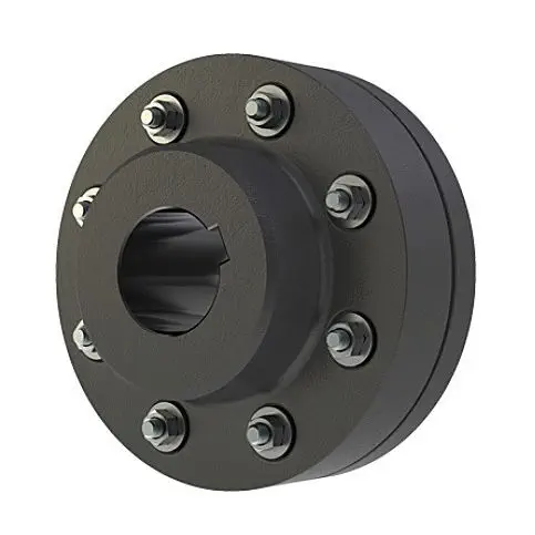
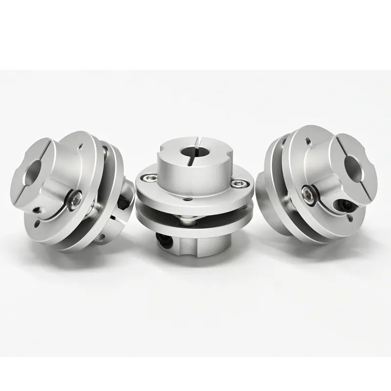
Flange couplings are mechanical devices used to connect two shafts and transmit torque between them. They come in various designs, each suited for specific applications. Here are the different types of flange coupling designs:
- 1. Unprotected Flange Coupling: This is the simplest type of flange coupling, consisting of two flanges with flat faces that are bolted together to connect the shafts. It is cost-effective and easy to install but offers limited protection against misalignment.
- 2. Protected Flange Coupling: In this design, the flanges are fitted with a protective cover or casing, which helps prevent dust, dirt, and other contaminants from entering the coupling. It provides better protection to the coupling components, making it suitable for outdoor or harsh environments.
- 3. Flexible Flange Coupling: This design incorporates a flexible element, such as a rubber or elastomeric insert, between the flanges. The flexible element allows for some misalignment between the shafts and helps dampen vibrations, reducing wear on connected equipment. It is commonly used in applications where there may be slight shaft misalignment.
- 4. Rigid Flange Coupling: The rigid flange coupling is a solid coupling without any flexible elements. It provides a rigid connection between the shafts, which is ideal for applications where precise alignment is critical, such as high-speed machinery or precision motion control systems.
- 5. Sleeve Flange Coupling: In this design, a hollow sleeve fits over the ends of the shafts and is bolted to the flanges. The sleeve helps provide additional support and alignment for the shafts.
- 6. Half-Flanged Coupling: Half-flanged couplings consist of two flanges on one shaft and a single flange on the other shaft. This design is suitable for applications with limited space or where one shaft is fixed, and the other requires disconnection frequently.
The choice of flange coupling design depends on factors such as the level of misalignment, speed of rotation, available space, environmental conditions, and the required level of flexibility. Proper selection of the flange coupling type ensures efficient power transmission and extends the life of connected machinery and equipment.


editor by CX 2024-04-25
by
Tags:
Leave a Reply