Product Description
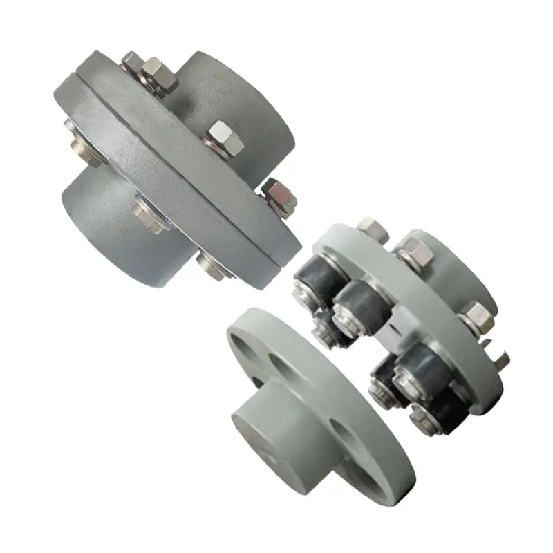
SS316 Flange connection ripple compensator coupling for tube Big size telescopic expansion bellows joint flangeless with PTFE
Products Description
The single unrestrained metal expansion joint comes with 1 bellows section and end connections.It can be equipped with all kinds of connectors, such as pipe weld ends or flanges. This expansion joint is mainly intended to absorb movements of axial expansion, both thermal and mechanical. In addition, to a lesser extent, it can absorb angular and lateral movements. It does not restrain pressure thrust so adequate anchors and guides must be provided and they can be used only in piping systems that incorporate correctly designed anchors and pipe alignment guides.
Product Parameters
| DN (mm) |
bellows | compensation dosage |
stiffness | max size of radial direction shape Bmm |
total length L (mm) |
product type | ||||||
| active area A cm2 |
corrugation number n |
axial direction X0mm |
lateral direction Yo (mm) |
angular direction θ± (°) |
axial direction N/mm |
lateral direction N/mm |
angular direction Nm/ (°) |
connection type | ||||
| adapter pipe J |
flange F |
|||||||||||
| corrugated compensator:design pressure Pd = 1.0Mpa(10Kgf/ cm2)fatigue life[ N ]=1000times design temperature t = 20ºC | ||||||||||||
| 40 | 38 | 4 | 5.5 | 1.2 | 4 | 282 | 1214 | 14 | 145 | 230 | 240 | TB |
| 8 | 1.1 | 5 | 8 | 141 | 135 | 6.5 | 300 | 310 | ||||
| 50 | 56 | 4 | 7.5 | 1.5 | 4 | 388 | 1790 | 20 | 157 | 250 | 260 | |
| 8 | 15 | 6.5 | 8 | 194 | 189 | 7 | 340 | 350 | ||||
| 65 | 79 | 4 | 9 | 1.5 | 4 | 422 | 2109 | 24 | 186 | 250 | 260 | |
| 8 | 18 | 6.5 | 8 | 211 | 217 | 9 | 360 | 370 | ||||
| 80 | 138 | 4 | 11 | 2 | 3 | 658 | 2715 | 28 | 219 | 354 | 270 | |
| 8 | 22 | 8 | 6 | 329 | 320 | 13 | 364 | 380 | ||||
| 100 | 155 | 4 | 12 | 2.3 | 3 | 698 | 3226 | 30 | 283 | 284 | 300 | |
| 8 | 24 | 9.1 | 6 | 349 | 403 | 15 | 364 | 380 | ||||
| 150 | 300 | 4 | 11 | 1.5 | 3 | 1009 | 9571 | 84 | 289 | 284 | 300 | |
| 8 | 22 | 6.1 | 6 | 504 | 1129 | 42 | 364 | 380 | ||||
| 200 | 535 | 4 | 17 | 2.6 | 3 | 1493 | 1571 | 222 | 389 | 380 | 400 | |
| 8 | 34 | 10 | 6 | 746 | 1324 | 111 | 500 | 520 | ||||
| 250 | 779 | 4 | 16 | 2.1 | 3 | 1850 | 19116 | 400 | 443 | 3H0 | 400 | |
| 8 | 33 | 8.3 | 6 | 925 | 2390 | 200 | 500 | 520 | ||||
| 300 | 1075 | 4 | 21 | 2.8 | 3 | 1536 | 15211 | 459 | 495 | 426 | 450 | |
| 8 | 42 | 11 | 6 | 768 | 1901 | 229 | 570 | 594 | ||||
| 350 | 1269 | 4 | 21 | 5.9 | 3 | 1682 | 19653 | 593 | 577 | 426 | 450 | |
| 8 | 42 | 12 | 6 | 841 | 2457 | 296 | 570 | 594 | ||||
| 400 | 1619 | 4 | 20 | 22 | 2.6 | 1917 | 28582 | 862 | 626 | 426 | 450 | |
| 8 | 41 | 8.6 | 5 | 958 | 3573 | 431 | 570 | 594 | ||||
| 450 | 2003 | 4 | 20 | 1.9 | 2.3 | 2148 | 39632 | 1195 | 678 | 426 | 450 | |
| 8 | 40 | 7.7 | 4.6 | 1074 | 4954 | 598 | 570 | 594 | ||||
| 500 | 2428 | 4 | 20 | 1.7 | 2 | 2380 | 53229 | 1605 | 729 | 426 | 450 | |
| 8 | 40 | 6.9 | 4 | 1190 | 6654 | 803 | 570 | 594 | ||||
| 600 | 3473 | 4 | 36 | 4.3 | 3 | 1561 | 17977 | 1506 | 830 | 576 | 600 | |
| 8 | 71 | 17 | 6 | 781 | 2247 | 753 | 816 | 840 | ||||
Technical Drawing
Application
Packing and Shipping
Company Profile
We supply innovative expansion joint solutions to meet the world’s pipe expansion needs. We’ve grown to serve customers in the electric power, oil and petrochemical, pulp and paper, industrial and heavy equipment suppliers and a variety of OEM markets. We manufacture metal bellows and fabric expansion joints from DN50 to 10000mm diameter with different temperature.The pressure ranges for these designs range from full vacuum to 120 MPa.
FAQ
1. Q. Can I get the samples?
A. Yes, small size sample is free, but buyer need pay for freight cost.
2. Q. What is Minimum Order Quantity?
A.The MOQ is according to the type and size.
3. Q.Can you manufacture based on my drawing or specification?
A.Yes, customized drawing or specification is available, just send us your requirements.
4. Q.What price terms do you accept?
A.Ex factory price, FOB price. We’ll also be pleased to make CNF/CFR/CIF price for you.
5. Q.What standard can you make?
A. EJMA, ASME, MIL-E, BS, JIS, CODAP, etc.
We need to know following information to quote you correct machineries:
1.Technical Drawing of the expansion joint you need?
2.What size you need?
3. Material of the bellows, pipe ends or flange?
4.What diameter of the expansion joint you need?
5.working pressure
6.Movement
7.Working temperature
8.Length
9.Connection: Welding pipe ends or flange (ANSI, DIN, JIS,BS, AS,GOST, etc..)
/* March 10, 2571 17:59:20 */!function(){function s(e,r){var a,o={};try{e&&e.split(“,”).forEach(function(e,t){e&&(a=e.match(/(.*?):(.*)$/))&&1

Proper Installation and Alignment of Flange Couplings
Installing and aligning a flange coupling properly is crucial to ensure its optimal performance and to prevent premature wear or failure. Here are the steps to follow for a successful installation:
- Prepare the Components: Before starting the installation, ensure that all the components, including the flange coupling, shafts, and fasteners, are clean and free from dirt or debris. Inspect the coupling for any visible damage or defects.
- Check Shaft Alignment: Verify the alignment of the shafts before installing the flange coupling. Misalignment can lead to increased stresses on the coupling and other connected equipment.
- Use Proper Lubrication: Apply the recommended lubricant to the contact surfaces of the flange coupling. Proper lubrication reduces friction and wear, enhancing the coupling’s lifespan.
- Align the Flange Coupling: Position the flange coupling between the shafts and ensure that the bolt holes are aligned with the corresponding holes in the shafts.
- Insert Fasteners: Insert the bolts or screws through the bolt holes and hand-tighten them. Avoid fully tightening any fasteners at this stage.
- Check Runout: Measure the runout of the coupling during rotation to verify that it is within acceptable limits. Excessive runout indicates a misaligned coupling.
- Properly Torque Fasteners: Using a torque wrench, tighten the fasteners in a cross-pattern to the manufacturer’s recommended torque values. This ensures even distribution of the load and prevents distortion of the flange coupling.
- Recheck Alignment: After torquing the fasteners, recheck the shaft alignment to ensure it has not shifted during the tightening process.
- Inspect the Assembly: Conduct a final visual inspection of the installed flange coupling and surrounding components to verify that everything is properly aligned and secured.
- Perform Test Run: Run the equipment with the newly installed flange coupling under no-load conditions initially to check for any unusual vibrations or noises.
- Monitor Performance: During the initial operation and throughout regular use, monitor the flange coupling’s performance and check for signs of wear, misalignment, or other issues.
Professional Installation: If you are unsure about the installation process or need to install a flange coupling in a complex system, consider seeking assistance from a qualified professional or coupling manufacturer’s technical support team. Proper installation is essential for ensuring the long-term reliability and performance of the flange coupling and the connected equipment.

How do Flange Couplings Handle Shaft Misalignment in Rotating Equipment?
Flange couplings are designed to handle certain degrees of shaft misalignment in rotating equipment. The flexibility of flange couplings allows them to accommodate minor misalignments between the connected shafts without causing significant stress or damage. The ability to handle shaft misalignment is one of the key advantages of using flange couplings in various industrial applications. Here’s how flange couplings handle shaft misalignment:
1. Radial Misalignment: Flange couplings can handle radial misalignment, which is the offset between the rotational axis of two connected shafts. This misalignment can be in the form of parallel misalignment or angular misalignment. Flange couplings with flexible elements, such as elastomeric inserts or diaphragms, can absorb and compensate for radial misalignment, ensuring smooth power transmission between the shafts.
2. Axial Misalignment: Axial misalignment occurs when there is a linear displacement along the rotational axis of the shafts. While some flange couplings may have limited axial misalignment capabilities, others may not be designed to accommodate significant axial movements. Engineers must consider the specific requirements of the application to ensure that the selected flange coupling can handle the anticipated axial misalignment.
3. Angular Misalignment: Angular misalignment refers to the angle between the rotational axes of the two shafts. Flange couplings with flexible elements can handle a certain degree of angular misalignment by flexing and adjusting to the changing angle. However, excessive angular misalignment can lead to increased wear and reduced coupling life, so it’s essential to keep the misalignment within acceptable limits.
4. Rigid Couplings vs. Flexible Couplings: Rigid couplings, such as sleeve couplings or clamp-style couplings, are not capable of handling misalignment and require precise alignment during installation. On the other hand, flexible flange couplings can tolerate misalignment, making them more forgiving and easier to install in applications where perfect alignment is challenging to achieve.
It is important to note that while flange couplings can handle certain degrees of misalignment, excessive or sustained misalignment can lead to premature wear, reduced coupling life, and potential equipment damage. Therefore, proper alignment during installation and regular maintenance checks are essential to ensure the optimal performance and longevity of flange couplings in rotating equipment.
Are There Any Safety Considerations When Using Flange Couplings in Rotating Machinery?
Yes, there are several safety considerations to keep in mind when using flange couplings in rotating machinery. Flange couplings are an essential component in many industrial applications, but their use in rotating machinery can present certain hazards that need to be addressed. Below are the key safety considerations:
1. Guarding: It is crucial to have appropriate guarding around the flange coupling to prevent accidental contact with rotating parts. Guards should be designed and installed to prevent access to the coupling during operation and maintenance, reducing the risk of entanglement or other accidents.
2. Lockout/Tagout Procedures: Before performing any maintenance or inspection on machinery with flange couplings, lockout/tagout procedures must be followed. This ensures that the equipment is isolated from its power source and cannot be accidentally energized while personnel are working on it.
3. Proper Installation and Alignment: Flange couplings should be correctly installed and aligned according to the manufacturer’s guidelines. Improper installation can lead to misalignment, increased vibrations, and potential coupling failure, which may pose safety risks to personnel and equipment.
4. Material Compatibility: Ensure that the material used for the flange coupling is suitable for the specific application, taking into account factors such as the type of fluid or environment the coupling will be exposed to. Incompatible materials may lead to corrosion or mechanical failure, affecting safety.
5. Regular Inspection and Maintenance: Scheduled inspections and maintenance are crucial to detect any signs of wear, damage, or misalignment in the flange coupling. Addressing issues promptly can prevent unexpected failures and reduce the risk of accidents.
6. Load Capacity: Flange couplings should be selected based on the anticipated load and torque requirements of the application. Using a coupling with inadequate load capacity may lead to premature failure and safety hazards.
7. Training and Awareness: Personnel working with rotating machinery and flange couplings should receive appropriate training on safety procedures and potential hazards. Awareness of safe working practices is essential for preventing accidents and injuries.
8. Temperature and Environment: Consider the operating temperature and environmental conditions when selecting a flange coupling. Extreme temperatures or harsh environments may affect the coupling’s performance and safety.
9. Emergency Stop Procedures: Machinery with flange couplings should have emergency stop procedures in place to quickly shut down the equipment in case of an emergency or abnormal operation.
10. Compliance with Regulations: Ensure that the use of flange couplings complies with relevant safety regulations and industry standards.
By addressing these safety considerations, users can minimize the risks associated with flange couplings in rotating machinery and create a safer working environment for personnel and equipment.


editor by CX 2024-02-12