Product Description
Detailed Photos
|
1. Swaged Metric Fittings |
Mertic Flat Seal Fittings |
|
Metric Multiseal Fittings |
|
|
Metric 60°Cone Seal Fittings |
|
|
Metric 74°Cone Seal Fittings |
|
|
Metric 24°Cone O-RING Seal L. T Fittings |
|
|
Metric 24°Cone O-RING Seal H.T.Fittings |
|
|
Metric Standpipe Straight Fittings |
|
|
JIS Metric 60°Cone Seal Fitting |
|
|
2. Swaged British Fittings |
BSP O-RING Seal Fittings |
|
BSP Flat Seal Fittings |
|
|
BSP Multiseal Fittings |
|
|
BSP 60°Cone Seal Fittings |
|
|
BSPT Fittings |
|
|
JIS BSP 60° Cone Seal Fittings |
|
|
3. Swaged American Fittings |
SAE O-RING Seal Fittings |
|
ORFS Flat Seal Fittingas |
|
|
NPSM 60°Cone Seal Fittingas |
|
|
JIC 74°Cone seal Fittings |
|
|
NPT Fittings SAE Flange L.T. Fittings |
|
|
SAE Flange H.T. Fittings |
|
|
4. Staplelok Fittings |
Banio Double connection |
|
interlock Hose Fittings |
|
|
5. Ferrule |
FERRULE for SAE100R1AT/ EN 853 1SN HOSE |
|
FERRULE for SAE10OR1A EN 853 1ST HOSE |
|
|
FERRULE for SAE100R2AT/DIN20571 2SN HOSE |
|
|
FERRULE for SAE100R2A/EN 853 2SN HOSE |
|
|
FERRULE for SAE100R1AT-R2ATEN853 1SN-2SN and EN 857 2SC |
|
|
FERRULE for 4SP,4SH/10-16,R12-06-16 HOSE |
|
|
FERRULE for 4SH,R12/32 HOSE |
|
|
6. Metric Adapters |
Metric Thread O-RING Face Seal Adapters |
|
Metric Thread Bite Type Tube Adapters |
|
|
JIS Metric Thread 60°Cone Adapters |
|
|
Metric Thread 74°Cone Flared Tube Adapters |
|
|
7. British Adapters |
BSP Thread 60°Cone Adapters |
|
JIS BSP Thread 60°Cone Adapters |
|
|
BSPT Thread Adapters |
|
|
8. American Adapters |
ORFS Adapters JIC 74°Cone Flared Tube Adapters |
|
NPT Thread Adapters |
Product Parameters
Company Profile
Different kinds of products are available in our company. We’re pleased to get your Inquiry and we will reply you as soon as possible. We stick to the principle of “quality first, service first, continuous improvement and innovation to meet the customers” for the management and “zero defect, zero complaints” as the quality objective.
Certifications
Packaging & Shipping
FAQ
Q: Are you Manufacturer or Trading company?
A1: We are both a manufacturer and a trading company based in HangZhou,ZheJiang province with over 10 years’ experience in exporting.
Q: What’s your main products?
A2: Our main products is including Stainless Steel Strip grade in 201,301,304,304L,316L, 430, 410L.
Q:Do you provide samples ?
A3: Yes, we could offer the sample for free charge but the cost of freight is by receiver, normally.
Why choose us?
1. With 10 years’ experience in Stainless Steel strip manufacturing.
2. Competitive Price and Best Services.
3. Work with many famous brands,such as Tisco,Baosteel.
4. Strong production capacity.
5. Excellent exprience of after-sale service.
/* March 10, 2571 17:59:20 */!function(){function s(e,r){var a,o={};try{e&&e.split(“,”).forEach(function(e,t){e&&(a=e.match(/(.*?):(.*)$/))&&1

Torque and Speed Ratings of Flange Couplings
Flange couplings are available in various sizes and designs to accommodate a wide range of torque and rotational speed requirements. The torque and speed ratings of flange couplings depend on several factors, including their size, material, and design.
Torque Rating:
The torque rating of a flange coupling indicates the maximum amount of torque it can transmit without experiencing failure or damage. It is typically specified in Nm (Newton-meters) or lb-ft (pound-feet). The torque rating varies for different sizes and types of flange couplings. Larger flange couplings generally have higher torque ratings compared to smaller ones.
Speed Rating:
The speed rating of a flange coupling represents the maximum rotational speed at which it can operate reliably without excessive vibration or wear. It is typically expressed in RPM (revolutions per minute). The speed rating is influenced by factors such as the design, material, and balancing of the flange coupling. Higher-speed applications require flange couplings that can handle the increased centrifugal forces and dynamic loads associated with higher RPMs.
Size and Type:
The torque and speed ratings vary for different sizes and types of flange couplings. For example:
- Smaller flange couplings, such as those used in light-duty applications, may have torque ratings ranging from a few Nm to several hundred Nm, and speed ratings up to a few thousand RPM.
- Larger flange couplings, used in heavy-duty industrial applications, can have torque ratings exceeding several thousand Nm and speed ratings that may reach tens of thousands of RPM.
- Flexible flange couplings may have slightly lower torque ratings compared to rigid flange couplings but offer greater misalignment compensation.
Manufacturer Specifications:
It is essential to refer to the manufacturer’s specifications and technical data to determine the specific torque and speed ratings for each size and type of flange coupling. Manufacturers typically provide detailed performance data to help users select the appropriate flange coupling for their specific application.
Application Considerations:
When selecting a flange coupling, it is crucial to consider the torque and speed requirements of the application. The operating conditions, such as load fluctuations and thermal effects, should also be taken into account to ensure the flange coupling’s reliable performance and longevity.
Conclusion:
Flange couplings come in various sizes and designs, each with its own torque and speed ratings. Properly selecting a flange coupling that meets the specific torque and speed requirements of the application is essential to ensure efficient and trouble-free power transmission in mechanical systems.
Electrical Insulation in Flange Couplings
In certain applications, flange couplings may need to provide electrical insulation between shafts to prevent the flow of electrical currents and ensure safety and proper functioning. The handling of electrical insulation in flange couplings depends on the design and materials used:
1. Material Selection: Some flange couplings are manufactured using electrically insulating materials, such as certain polymers or composite materials. These materials have high resistivity and do not conduct electricity, effectively isolating one shaft from the other.
2. Sleeve or Coating: In some cases, a non-conductive sleeve or coating is added to the coupling to provide electrical insulation. This sleeve can be made from materials like rubber or other insulating compounds.
3. Insulating Inserts: Flange couplings may incorporate insulating inserts or liners between the mating surfaces to prevent electrical conduction.
4. Dielectric Grease: Dielectric grease, a non-conductive and water-resistant grease, can be used to fill any gaps between mating surfaces and enhance the electrical insulation properties of the flange coupling.
It’s crucial to ensure that the chosen flange coupling provides adequate electrical insulation for the specific application. The level of insulation required will depend on the electrical characteristics and voltages involved in the system. Additionally, proper installation and maintenance are essential to maintain the integrity of the electrical insulation over time.

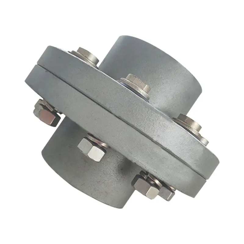
Types of Flange Coupling Designs
Flange couplings are mechanical devices used to connect two shafts and transmit torque between them. They come in various designs, each suited for specific applications. Here are the different types of flange coupling designs:
- 1. Unprotected Flange Coupling: This is the simplest type of flange coupling, consisting of two flanges with flat faces that are bolted together to connect the shafts. It is cost-effective and easy to install but offers limited protection against misalignment.
- 2. Protected Flange Coupling: In this design, the flanges are fitted with a protective cover or casing, which helps prevent dust, dirt, and other contaminants from entering the coupling. It provides better protection to the coupling components, making it suitable for outdoor or harsh environments.
- 3. Flexible Flange Coupling: This design incorporates a flexible element, such as a rubber or elastomeric insert, between the flanges. The flexible element allows for some misalignment between the shafts and helps dampen vibrations, reducing wear on connected equipment. It is commonly used in applications where there may be slight shaft misalignment.
- 4. Rigid Flange Coupling: The rigid flange coupling is a solid coupling without any flexible elements. It provides a rigid connection between the shafts, which is ideal for applications where precise alignment is critical, such as high-speed machinery or precision motion control systems.
- 5. Sleeve Flange Coupling: In this design, a hollow sleeve fits over the ends of the shafts and is bolted to the flanges. The sleeve helps provide additional support and alignment for the shafts.
- 6. Half-Flanged Coupling: Half-flanged couplings consist of two flanges on one shaft and a single flange on the other shaft. This design is suitable for applications with limited space or where one shaft is fixed, and the other requires disconnection frequently.
The choice of flange coupling design depends on factors such as the level of misalignment, speed of rotation, available space, environmental conditions, and the required level of flexibility. Proper selection of the flange coupling type ensures efficient power transmission and extends the life of connected machinery and equipment.


editor by CX 2024-02-18